FPGA based Digital World
Welcome to FPGA based Digital World.
Analog circuit is the basis of electronics, and covers lots of area. |
Basic Laws
Phasor Ralatiohships for Circuit Elements
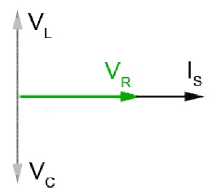
For resistor R, capcitor C and inductor L, the voltage-current relationships are listed below.
| Element | Time Domain | Phasor/Frequency domain |
| R | v=Ri | V=RI |
| C | v=Ldi/dt | V=jωLI |
| L | v=Cdv/dt | V=I/jωC |
And it's also illustrated graphically.
[Example] The voltage v(t)=9cos(2t+30°)is applied to a 10mH inductor, calcuate the steady-sate current through the inductor.
Solution:
The source phasor is: V = 9*exp(30°), ω=2 rad/s
--> I=V/jωL = 9*exp(30°)/j(2*0.01)=9*exp(30°)/(0.2*exp(90°))=45*exp(-60°)A
--> i(t)=45*cos(2t-60°)
Basic Laws in Phasor Doamin
Ohm's law, Kirchhoff's laws of KVL and KCL are still valid in phasor domain.
Ohm's Law in Phasor Form
V=ZI
where V and I are phasor voltage and phasor current,
Z is the impedance, measured in ohms(Ω).
(Note: Z is not a phasor, and not corresponds to a sinusoid)
Impedance Z can be expressed in rectangular form as
Z=R+jX
where R is resistance and X is reactance, measured in ohms.
Admittance Y is the reciprocal of impedance, in the rectangular form as
Y=1/Z=I/V
Y expressed in rectangular form is
Y=G+jB
where G is conductance and B is suscptance.
The relationship between R,X and G, B is
G=R/(R*R+X*X), B=-X/(R*R+X*X)
KCL in Phasor Form
Kirchhoff's current law(KCL) applies to a node, and is based on the law of conservation of charge.
The sum of current phasors entering a node(or a closed boundary) is zero:
I1 + I2 +... + In = 0
KVL in Phasor Form
Kirchhoff's voltage law(KCL) applies to a loop , and is based on the law of conservation of energy.
The sum of all voltage phasors around a loop(or a closed path) is zero:
V1 + V2 +... + Vn = 0
| Altera/Intel | Xilinx | Lattice | Learn About Electronics |
| MircoSemi | Terasic | Electric Fans |
| All rights reserved by fpgadig.org |
| Electric Device |
| Diode |
| Bipolar Junction Transistor |
| Field Effect Transistor |
| Operational Amplifier |
| FPAA |
| Circuit Analysis |
| DC Circuit |
| Basic Laws |
| Basic Analysis Techniques |
| Linear Circuit |
| Analysis Theorem in Linear Circuit |
| AC Circuit |
| Sinusoidal Steady-State Analysis |
| Sinusoid and Phasor |
| Basic Laws |
| Analysis Techniques |
| Frequency Response |
| Non-Sinusoid Steady-State Analysis |
| Transient Analysis |
| First Order Circuits |
| Second Order Circuits |
| Two-port Networks |
| Related Knowledge |
| Waveforms in Electric Circuit |
| Power Supply |
| Linear Regulator |
| SMPS Basic Topology |
| SMPS with Transformer |
| SMPS without Transformer |
| Clock Generation |
| EDA Tools |
| Technical Notes |
| DC-DC Test |